

Temporary Grounding Sets for Power Lines
Temporary grounding sets for power lines are critical safety equipment used by utility workers when performing maintenance, repairs, or construction on de-energized (or presumed de-energized) overhead power lines or equipment within substations. The purpose is to protect workers from:
Accidental Re-energization: The line being inadvertently re-energized from either end.
Induced Voltages: Voltages induced on the de-energized line from adjacent energized lines (especially common on transmission lines running parallel to live circuits).
Capacitive Discharge: Residual charges on the line after de-energization.
Lightning Strikes: Providing a safe path to ground for any lightning strikes during the work.
By applying these grounds, workers create an equipotential zone, ensuring that if the line becomes accidentally energized, the fault current will bypass the worker and safely dissipate to the earth, causing protective devices to trip rapidly.
Components of a Temporary Grounding Set:
A complete temporary grounding set typically consists of the following key components, often assembled as a "kit":
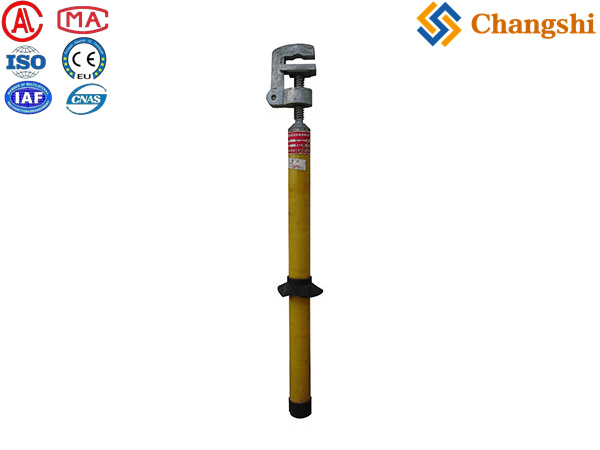
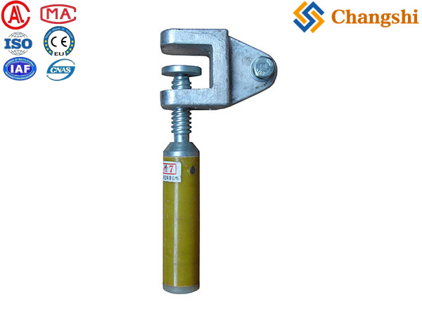
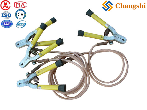
Grounding Clamps (Line-End and Earth-End):
Purpose: To make secure, low-resistance electrical connections to the conductor(s) and to an established earth ground point (e.g., ground rod, substation ground grid).
Types:
"C" Clamps: Very common for various conductor sizes and busbars. (Mentioned in search results from JM Test Systems, J Harlen Co., Mueller).
Duck-Bill / Flat-Jaw Clamps: For flat busbars or certain conductor configurations.
Ball Clamps / Clamp Sticks: For connecting to permanent ball-stud grounding points found in substations.
"Cluster" Clamps: Connect multiple phase leads to a single ground point.
Materials: High-conductivity alloys like aluminum (lighter weight) or bronze (more durable, higher current carrying capacity).
Features: Often have serrated jaws for better grip, spring-loaded for initial hold, and an eye-screw or operating ferrule for hot stick application.
Grounding Cables / Leads:
Purpose: To provide a low-resistance path for fault currents between the clamps and to the earth.
Material: Highly flexible, stranded copper conductors are standard due to their excellent conductivity and flexibility.
Insulation: Durable, transparent PVC or rubber insulation allows for inspection of the conductor. The insulation is not for electrical insulation during a fault, but for mechanical protection and to prevent accidental shorting during application.
Gauge/Size: Measured in AWG or mm². Sizes like 1/0, 2/0, 4/0 AWG are common, chosen based on the potential fault current levels of the system being worked on. (J Harlen Co. search results show these sizes).
Lengths: Available in various lengths (e.g., 6ft, 8ft, 10ft, 12ft, 20ft, 40ft as seen from J Harlen Co.), allowing for proper placement and minimizing cable whipping during a fault.
Terminations: Equipped with durable ferrules (crimps) for secure attachment to the clamps, designed to withstand high fault currents without overheating or detaching.
Insulated Hot Sticks / Operating Poles:
Purpose: Crucial for safely applying and removing grounding clamps from a distance, maintaining electrical isolation between the worker and the conductor.
Materials: High-strength, fiberglass reinforced plastic (FRP) with excellent dielectric properties.
Types: Sectional, telescopic, or "shotgun" style, with universal heads compatible with the grounding clamps' operating ferrules. (Taurus Powertronics search result explicitly mentions hot sticks for "installing Temporary Grounding Sets").
Temporary Ground Rods (optional but common):
Purpose: To establish a good earth connection in locations where a permanent ground grid isn't available (e.g., remote overhead line sections).
Description: Shorter, robust copper-bonded steel rods that can be driven into the ground quickly.
Storage Bags/Cases:
Purpose: To protect the grounding set components from damage and keep them organized during transport and storage.
Design Considerations & Standards:
Temporary grounding sets are not "one-size-fits-all." They must be selected and used based on:
System Voltage: The nominal voltage of the line or equipment (e.g., 15kV, 35kV, 115kV, 345kV).
Available Fault Current: The maximum short-circuit current that could flow at the grounding point, and for how long. This is the most critical rating for the cables and clamps.
Conductor Type and Size: To ensure clamps fit securely.
Operating Environment: Weather resistance, temperature ranges.
Safety Standards: Compliance with international standards like ASTM F855 (Standard Specification for Temporary Protective Grounds to be Used on De-energized Electric Power Lines and Equipment), ASTM F2249, IEC 61230, and NFPA 70E. These standards define the mechanical and electrical performance requirements (e.g., short-circuit current withstand, clamping force).