

Grounding & Earthing Equipment
Grounding (US terminology) or earthing (UK/IEC terminology) equipment is fundamental to the safety and reliability of any electrical power system, from generation to transmission, distribution, and consumption. Its primary purpose is to provide a safe path for fault currents to dissipate into the earth, thereby protecting personnel from electric shock, safeguarding equipment from damage, and ensuring the stable operation of the electrical system.
Core Principles of Grounding/Earthing:
Safety (Personnel Protection): When a fault occurs (e.g., a live wire touching an equipment casing), grounding provides a low-resistance path for the fault current to flow to the earth. This causes protective devices (like circuit breakers or fuses) to trip, isolating the fault and preventing dangerous touch potentials that could injure or kill a person.
Equipment Protection: By providing a path for fault currents, grounding limits overvoltages that could otherwise damage sensitive equipment during faults, lightning strikes, or switching surges.
System Stability: Grounding helps stabilize system voltages, especially during faults, ensuring that the electrical system operates within safe parameters. It provides a reference point (earth potential) for the entire system.
Lightning Protection: A properly designed grounding system safely dissipates lightning strike energy into the earth, protecting structures and equipment.
Types of Grounding & Earthing Equipment for Power Utilities:
A. Grounding Electrodes & Conductors (The "Earth Connection"):
These are the components that make direct contact with the earth to establish a low-resistance path.
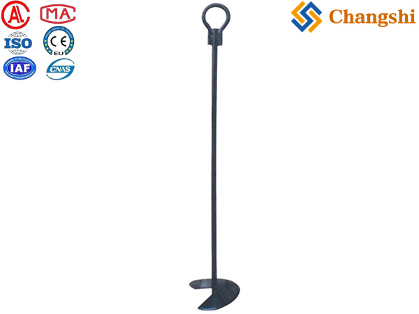
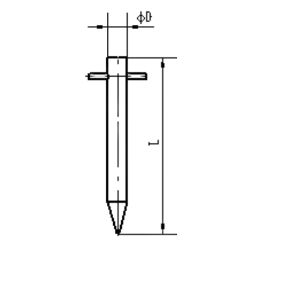
Earth Rods / Ground Rods:
Description: Long, metallic rods driven vertically into the ground. They are the most common type of earth electrode.
Materials: Typically made of copper-bonded steel (steel core with a thick copper plating for conductivity and corrosion resistance), pure copper, or stainless steel (for highly corrosive environments).
Installation: Driven into the earth using hammers, vibratory drivers, or specialized tools. Multiple rods can be connected using couplers to reach deeper, lower resistivity soil.
Earth Plates / Ground Plates:
Description: Flat, rectangular or square metallic plates buried horizontally in the ground. They offer a larger surface area than rods in shallower depths.
Materials: Copper or galvanized iron/steel.
Applications: Used where soil resistivity is high at shallow depths, or where a large surface area is required.
Earth Mats / Grid Conductors:
Description: A network of interconnected bare conductors (typically copper or galvanized steel) buried horizontally in a grid pattern.
Applications: Essential for substations and power plants to establish an equipotential plane across the entire site, minimizing step and touch potentials during fault conditions.
Counterpoise:
Description: A system of radial conductors buried just below the surface, extending outwards from a tower or structure.
Applications: Used in high-resistivity soil or rocky terrain where driving deep earth rods is impractical, to effectively reduce tower footing resistance.
Exothermic Welds (e.g., nVent ERICO Cadweld):
Description: A permanent, molecular bond for connecting grounding conductors (e.g., wires to ground rods, or grid conductors to each other). This creates a highly reliable, low-resistance connection that doesn't loosen over time.
Advantages: Superior to mechanical clamps for permanent installations due to low resistance, high current carrying capacity, and corrosion resistance.
B. Portable Grounding & Earthing Equipment (for Safety During Maintenance):
These are temporary grounding solutions used by utility workers to ensure safety when working on de-energized lines or equipment. The principle is to create a "zero-potential zone" around the work area by connecting phases together and then to an established earth ground.
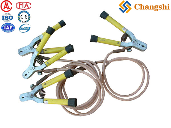
Portable Earthing & Short-Circuiting Kits:
Components: Consist of:
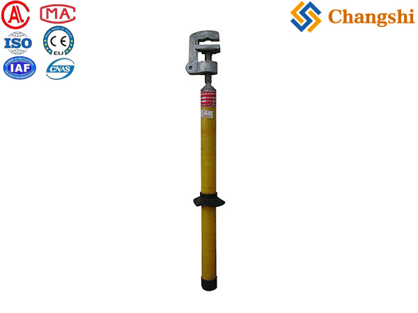
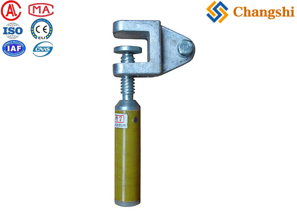
Grounding Clamps: High-conductivity clamps (bronze, aluminum alloy, or copper) designed to securely attach to conductors, busbars, or ground points. Types include "C" clamps, ball clamps, duck-bill clamps, etc., suitable for various conductor sizes and types.
Grounding Cables / Leads: Flexible, high-current-capacity cables (copper or aluminum) with durable insulation, designed to withstand fault currents. They connect the clamps to each other and to the earth point. Often supplied as "grounding clusters" (multiple leads connected to a common ground point).
Insulated Hot Sticks/Operating Poles: Non-conductive poles used to safely apply and remove grounding clamps from energized (or potentially energized) conductors from a safe distance.
Ratings: Kits are rated for specific fault currents (kA) and duration (seconds) they can safely carry without melting or damaging components.
Applications: Used on transmission lines, distribution lines, and within substations to temporarily ground lines and equipment before work begins.
Grounding Busbars and Supports:
Description: Solid copper bars used as common connection points for grounding conductors within substations, switchgear, or equipment enclosures.
Function: Provides a neat, organized, and effective point for multiple ground connections.
C. Testing & Monitoring Equipment:
Earth Resistance Testers / Ground Resistance Testers:
Description: Specialized instruments used to measure the resistance of the earth electrode system.
Importance: Crucial for verifying the effectiveness of the grounding system and ensuring it meets design specifications and safety standards. Methods include 3-point (fall-of-potential), 4-point, and clamp-on (for continuous loops).